
Perspective
Constructions
¤ Perspective Reconstruction
¤ First Cube as Extreme Cube
¤ Focusing Target Corner
¤ Cast Shadows by Freehand
¤ Windows
¤ Building and Plants
Outdoor Assignments
Special Courses
Publications
STRUCTURAL BASIC GRID'S APPLICATION IN ORDER TO HELP CAST SHADOW CONSTRUCTION IN PERSPECTIVE RENDERING BY FREEHAND |
||||||
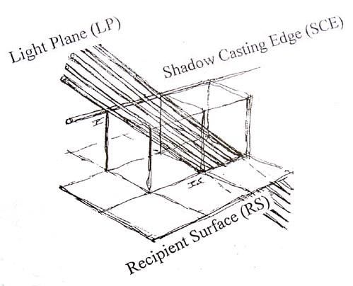
Key-words: Framing Shape of Light (FSL), Light Plane (LP), Orthogonal Picture, Plane Diagonal, Principal Light Beam (PLB), Recipient Surface (RS), Shadow Casting Edge (E), Shadow Casting Point (P), Source of Light, Spatial Diagonal. |
||||||
| Introduction | ||||||
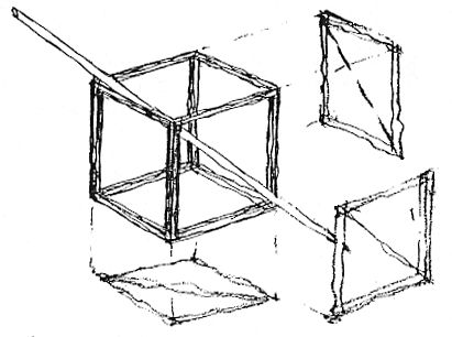
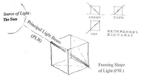
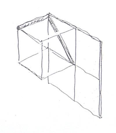
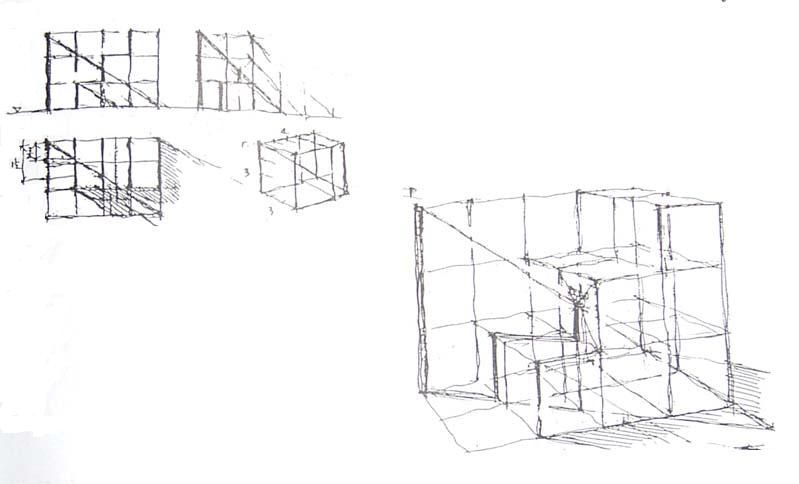
According to my personal method described below, let's envisage the direction of the Principal Light Beam (PLB) as if it were a spatial diagonal of a simple cube modeling the Framing Shape of Light (FSL)! |
||||||
|
||||||
|
||||||
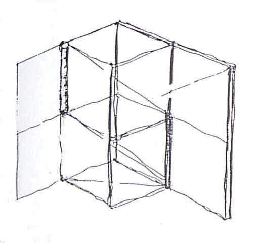
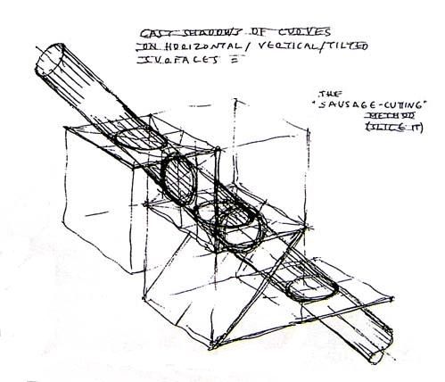
Answering plane diagonals of the FSL-box correspond to the selected light beam's orthogonal pictures. It is more convenient to find intersections between the Light Plane (LP) and the Recipient Surface (RS) in their orthogonal pictures first. These very intersections represent cast shadows' borders we are looking for. We derive the Light Plane (LP) from having set a series of light beams parallel to the Principal Light Beam (PLB) along the Shadow Casting Edge (SCE) in question. |
||||||
|
||||||
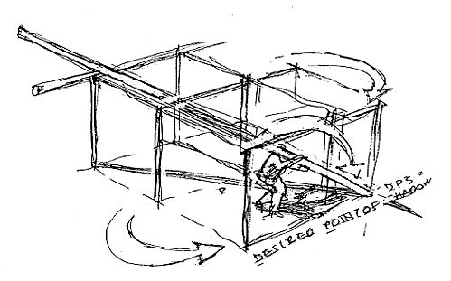
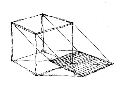
| As to start with we may presume that the Principal Light Beam's position would exactly coincide with the corresponding spatial diagonal of the cube (called Framing Shape of Light). In order to get the cast shadow on the floor of the upper corner (P) we place the principal light beam (now: the spatial diagonal) on it. This will point exactly to the opposite bottom corner (PS). The cast shadow of the upper corner is at the opposite bottom corner. | ||||||
|
||||||
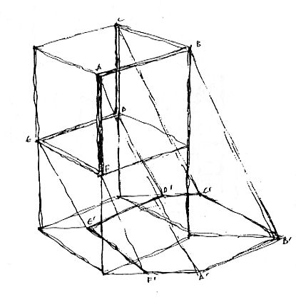
As for the cast shadow of the first chosen point (P) we may freely determine its piercing through the recipient surface. This will be the Desired Point of Cast Shadow (DPS). Here we generally make our choice guessing the best possible final outcome of the whole picture to be completed with constructed cast shadows. |
||||||
|
||||||
5. The Desired Point of Shadow. Moving PS to PDS means a construction step backwards. |
||||||
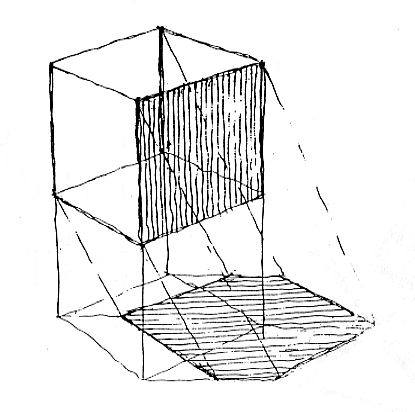
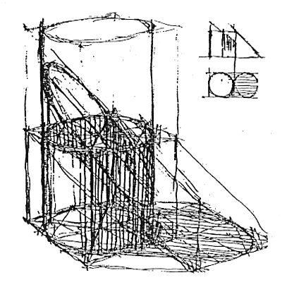
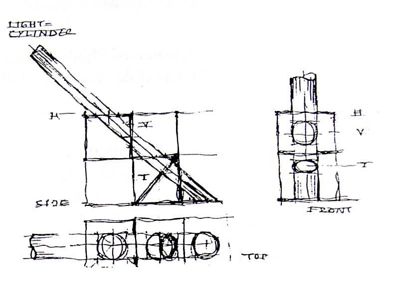
By connecting the Desired Point of Shadow (DPS) with the initial Shadow Casting Point (P) we settle in perspective the true direction of light we are from now on working with. This will finally shape the new spatial diagonal of our modified Framing Shape of Light. After this starting procedure we may ascertain in three orthogonal pictures (top- front- and side views) the definitive proportion between adjoining sides of the Modified Framing Shape of Light. While constructing cast shadows in perspective, we should carefully follow the answering projected pictures of the light beam in its orthogonal pictures (L', L", L"') as well. In the following let's sum up the most frequent basic situations modeled within the structural basic grid! We should study these simplified cases first in order to solve more complicated situations later. |
||||||
6 - 9: Most frequent cast shadow situations within the Structural Basic Grid (in parentheses: cause and result). |
||||||
|
||||||
|
||||||
EXAMPLES |
||||||
|
||||||
The selection procedure of Shadow Casting Edges (SCE) means to settle a reasonable boundary between light and dark surfaces. Shadow Casting Edges of solid objects formulate a continuous line resulting finally in a closed cast shadow area. Check interim convergence of parallels even during shadow construction! |
||||||
|
||||||
|
||||||
|
||||||
| Construction steps: • Cast Shadow of the Top Plane • Circle construction (supported by octogonal tangents) • Circle / Square / Tangents / Vertical borders |
||||||
|
||||||
|
||||||
|
||||||
ASSIGNMENTS |
||||||
| 1 - Cast shadow of a mast on a flight of stairs modeled by cubes | ||||||
|
||||||
| 2 - Cast shadow of a ladder on a terraced heap of cubes | ||||||
|
||||||
| 3 - Light Stripe of an upper row window | ||||||
|
||||||
|
||||||
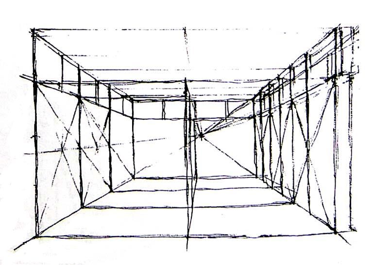
20. Perspective sketch of the hall. |
||||||
|
||||||
|
||||||
SUMMARY |
||||||
Initially we may presume that the Principal Light Beam's position exactly coincides with a cube's spatial diagonal. We name this virtual cube as the "Framing Shape of Light". By connecting the Desired Point of Shadow (DPS) with its corresponding Shadow Casting Point (P) we settle in perspective the true direction of light beam. After this starting procedure we may easily ascertain in orthogonal pictures the definitive proportion of the Modified Framing Shape of Light. |
||||||
© All rights reserved Associated Professor Balazs Mehes PhD recommended resolution 1024×768 |
||||||