|
| |
FIRST CUBE as EXTREME CUBE
|
|
Exploiting Orthogonal Views in order to construct by Freehand the Starting Cube of the Structural Web of Basic Lines
|
|
The "Paper Band" Method
|
|
|
|
Key-words: Central projection, the Diagonal Method, Extreme Oblique Line, Framing Shape, Halving Plane, Hexagon-Outline, the Object Picture Plane, Oblique Lines of In-Between, Orthogonal Picture, Preliminary Proportion of Lateral Planes, Principal Visual Ray, Proportion, Structural Web of Basic Lines, the Vanishing Point, View-Point, Visual Ray. |
| |
Summary
|
The most sensitive part of assignments dealing with perspective reconstruction through orthogonal pictures is the sketching by freehand with a chosen view-point the starting cube. We need the first cube in order to create the structural grid of basic lines. Our first cube should be an extreme cube of which steeply converging edges do relate to remote Vanishing Points being frequently off paper size. Through the Diagonal Method the cubic grid might be afterward enlarged.
Sketching our starting cube by heart can powerfully be supported by preliminary proportion of lateral planes taken from related orthogonal pictures. Distances between vertical edges might be metered from the top plan rotated into principal visual ray direction, reading data arising on the Object Picture Plane. We may take over the distortion of horizontal planes from the Halving Plane.
While bringing into cover in our perspective sketch these two projective stripes belonging to the cube's edge in question, the extreme oblique line relating toward the Vanishing Point will soon become distinct.
Through fixing our view-point we may preliminarily decide the visibility proportion between lateral planes of the cube. Choosing the picture distance the true value of "sight-from-below" will be determined. In order to evaluate the position of the extreme oblique edge we exploit these two previous decisions. |
|
|
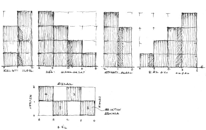
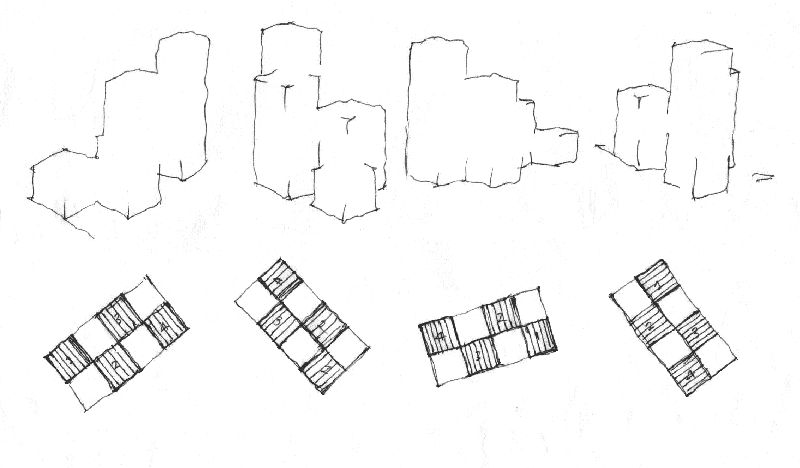
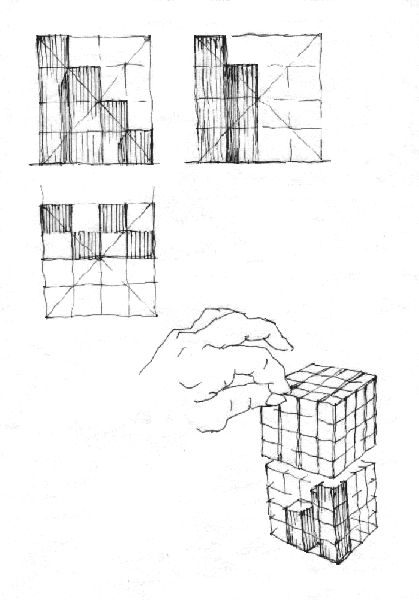
1. Terraced towers of cubes placed on a quadratic grid
Let's prepare a perspective view of the volume confirmed here by its orthogonal pictures!
Let us determine distortions belonging to the most remote square plane by using of proportion data taken from the plan (rotated into view-point direction) and from the halving plane which emanate the ratio of the "sight-from-below"! |
|
|
|
| |
2. By revolving the plan we establish the correct view-point direction. |
|
|
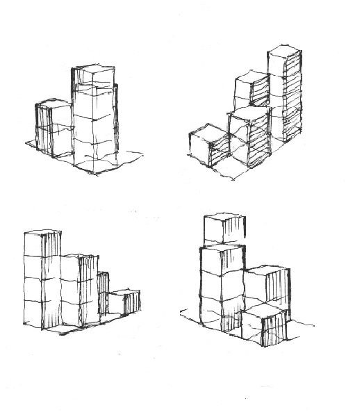
3. Model-drawings help us to choose favorable view-points. During the preparatory stage let's create several volume sketches from every direction as well, as seen out of birth-eye level! |
|
|
4. Outlines with concerning plans turned into view-point direction. We imagine relating view-points as being at drawing paper's lower edge. |
|
|
|
|
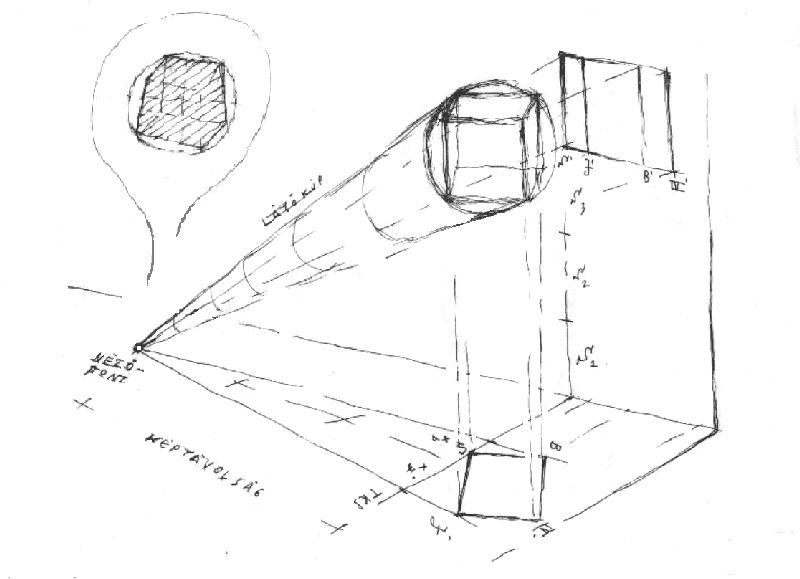
5. Main dimensions of the framing hexagon (related to the chosen cube).
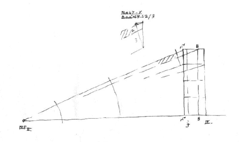
That's how the extreme cube looks like as seen from the view-point. Its total height is an addition of the nearest vertical edge and of the virtual height of the lower plane (M = S + a). Its total largeness is a sum made of smaller and bigger lateral side-sections (Sz = xbal + xjobb). As far as picture distance is not less than two-and-a-half of the object, the picture plane's inclination won't be significant, meaning that verticals do not distort yet. By moving our view-point closer, a third vanishing point will appear. |
|
|
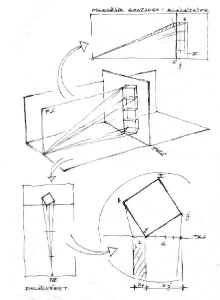
6. The "Halving Plane" derives from the plan turned into view-point-position.
We shall read extreme "sights-from-below" relations by examining the "Halving Plane". The Halving Plane is a special side view coordinated to our chosen view-point at the beginning. We imagine its position being perpendicular both to the ground plan and to the object's picture plane as well. Here in our example, within this special side view all vertical edges of the cube appear one by one. With the help of a paper band we may copy over their precise orthogonal position from the plan (turned into view-point position) to the Halving Plane. |
|
|
|
|
7. Sections X
|
The preliminary choice of lateral sides' sections follows also in the opposite direction. We revolve the square (inserted by its nearest corner to the object picture plane) on the plane as far as both visual rays launched from the view-point (NP) toward extreme corners (B, J) will dissect (within the object picture plane) the desired lateral sides' ratio.
|
|
|
8. Evaluating the stripe of the "big Y" (Y/S)
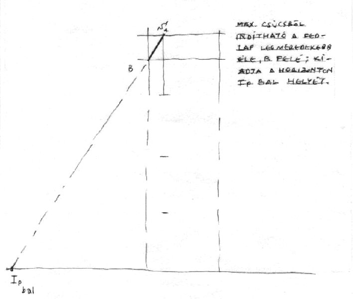
We connect our view-point (NP) with the highest corner of the tower-edge (Smax) as well, as with the left corner of the top square (B). We understand the virtual height of this stripe within the line of the object picture plane which, in case of a remote view-point, doesn't differ much from the vertical. (The value of this section here is about 2/3 S.) Now the near vertical edge of our perspective cube under construction might be dissected into five parts. At the upper two-fifths we may mark the lower end of the stripe called "big Y". |
|
|
9. Orthogonal stripes' overlapping zones will deliver the direction of the extreme oblique line. Next we may guess the position of the other (remote) vanishing point. |
|
|
|
|
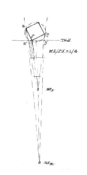
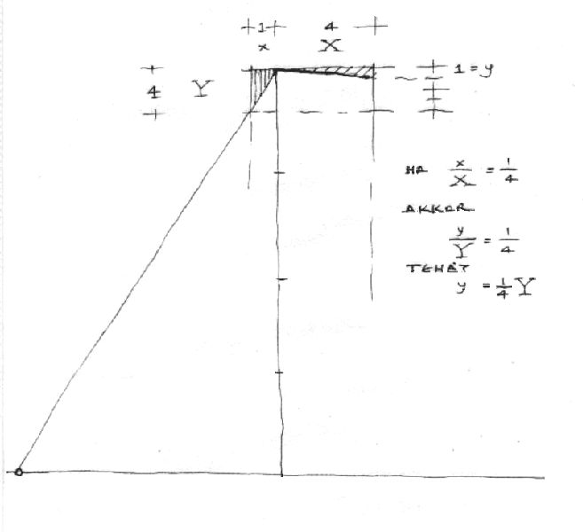
10. Position of corners - an "opposite ratio"
If horizontal distances between vertical edges are here (as initially chosen):
x / X = 1/4
then y / Y = 1/4,
for this reason the virtual pending of the right corner is about a fourth of the left one.
(small y =
1/4
big Y). |
|
|
11. Extension of the structural grid
Before extending the structural grid by the help of the "Diagonal Method", we ought to check from every direction our extreme cube's credibility. During this proceeding we should to a greater extent observe backside squares which reveal eventual errors sooner than frontal ones. |
|
|
|
|
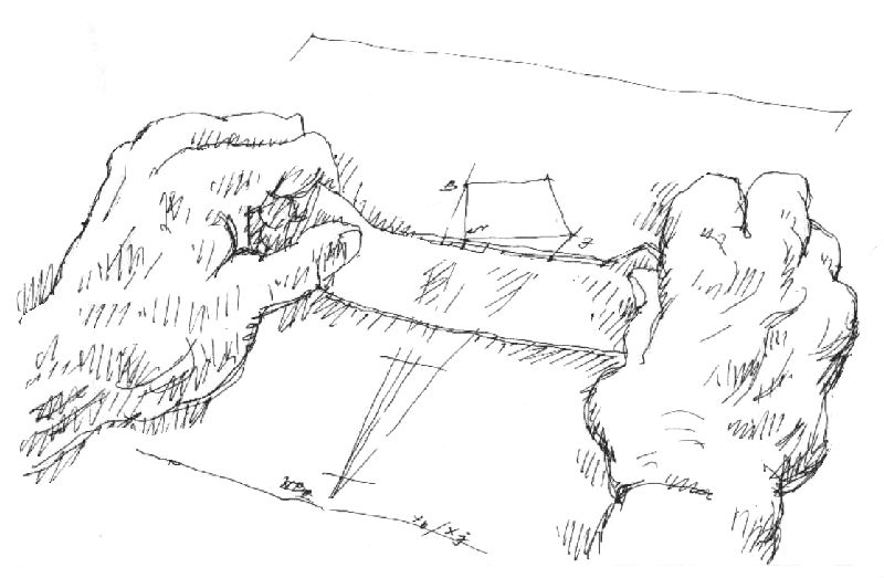
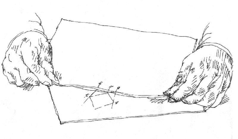
12. The "Paper Band" Method - we may conserve orthogonal sections by using the edge of a fresh page.
|
|
|
13. Enveloped into a big cube
The final figure shows the same task approached in a different way. Some times the volume waiting to be depicted needs a single enveloping cube of enormous size only.
Even in this case we accomplish our starting construction within the big cube's cover plane - that means at the largest distortion to be expected. Later on, by consequently applying of diagonals, going through mid-sections of border planes, we shall finally reach the grid's appropriate joints of in-between. |
|
|
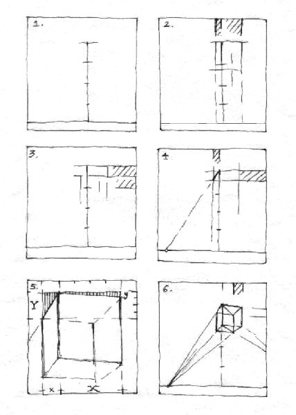
14. Orthogonal pictures for sketching the structural grid's starting cube - six pictograms
(a) We may freely choose the horizon and the tower's size. The framing shape advances the project's outline.
(b) Reading the plan turned into view-point direction we establish the lateral sides' ratio.
(c) Regarding the "Halving Plane" we determine the proportion of "sight-from-below" which belongs to the extreme cover plane.
(d) After having brought these two orthogonal stripes into overlapping position, the extreme oblique line appears, showing us the location of the nearer vanishing point.
(e) We may guess the where-about of the other vanishing point if we consider the opposite ratio existing at reverse corners' virtual heights.
(f) Our first paper band delivers even the position of the fourth (backside) vertical edge. The vanishing point of diagonals might be also used for controlling convergences. |
|
|
| |
|
| |
![]() © All rights reserved Associated Professor Balazs Mehes PhD
© All rights reserved Associated Professor Balazs Mehes PhD
recommended resolution 1024×768
|