Perspective

  ¤ Basic Concepts of Linear Perspective
  ¤ "Illustrated Drawning of Cubic Forms"
  ¤ "The Master Picture Plane"
  ¤ Reflected Tower Trio
 
¤ Circular Rings
  ¤ Furniture Drawing
  ¤ Corridor Drawing


   Constructions


   Outdoor Assignments


   Special Courses


   Publications
 

The "MASTER PICTURE PLANE"

Teaching Phenomena of Linear Perspective

 
Key-words:

    •     Extreme Oblique Line
    •     Halving Plane
    •     Master Picture Plane
    •     The Pencil Method
    •     Principal Directions
    •     Proportion Measuring Method
    •     Structural Web of Basic Lines


My first experiments at the Dep. of Drawing/TUB with the Master Picture Plane (Cubic bodies for first-year students in civil engeneering, Fall 2000)


Introduction


Looking through the Master Picture Plane
     The demonstration of my help called "Master Picture Plane" seems to be appropriate at the beginning of teaching the theory of linear perspective, while dealing with its basic phenomena.
     In the course of making the structure of Architectural Freehand Drawing the exacte depicting of oblique lines is very important. For many students the origine of the "Pencil-Method" (= measuring with a streched arm) is generally obscure.
     The illusion of depth in pure-line-drawing is mainly due to those tilted lines. We underline here the importance of tilted lines perceived being tilted while comparing them to external edges of the picture plane (or rather: to those of the drawing paper). These edges of our oblonge-shaped drawing paper represent safely the principal directions.
 
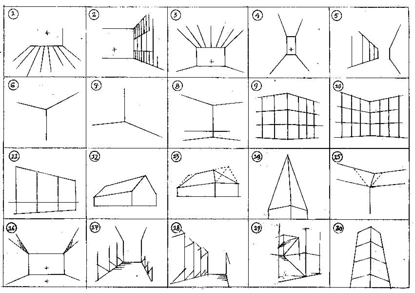
     Our principal directions in drawing are Horizontal and the Vertical lines. We analyse the remaining oblique lines by subdividing them into their components belonging to principal directions. After having reduced the subject to simple straight lines, all we have to depict remains a boundle of lines running either parallelly to main directions or being slanting. The careful observation of oblique lines in the structural grid is an important sketching phase.


Components of the Teaching Help


    •     Drawing Plane
    •     Observation Plane
    •     Joints
    •     Supporting bar
    •     Measuring stick
    •     Additional parts: record rings


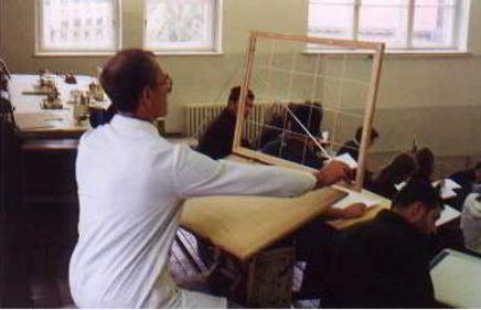
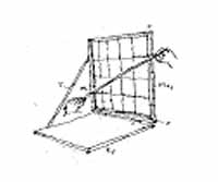
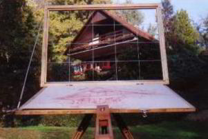
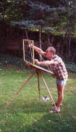
     Thin plastic wires subdivide the wooden frame of "Master Picture Plane" into equal squares. The frame is joint by turning links to the upper edge of the drawing board. After having experienced some few times with it, we'll take off the frame. Let's freely develop now the "compas in the eye"! The supporting bar has a telescopic joint apt to follow the picture plane's needed observing position.
     We carefully examine some points of junction within the structural web of basic lines. Let us determine one by one the obliquity of these extreme tilted lines! Attention: everybody will have his or her individual point of view to which a special rate of distortion belongs.


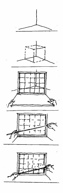
     How to use the Master Picture Plane? Let's examine for example a common lower "Y-shaped" junction!


The combined use of Master Picture Plane and the Proportion Measuring Method


(A) That's what we see looking into the near bottom        corner of the drawing room.


(B) The situation coincides with the arrangement of        backside edges of the structural basic cube.


(C) That's how the sight appears within the frame of         the Master Picture Plane.


(D) We cover the chosen oblique line with the         measuring stick moved in the frame's plane         and, in the same time we enlarge it until the         edge of the frame.


(E) In order to determine easier the values of         perpendicular sides of the right angle, we let         slip down the stick used as a hypotenuse to the         basic line. Finally we take over the calculated         ratio of proportion to the drawing's plane.


20 Examples for Practizing with the Help


    •     A floor-net of squares
    •     A row of windows
    •     Ceiling beams
    •     A Corridor-like longitudinal space
    •     Street walls
    •     Y-shaped junction, upper part
    •     Y-shaped junction, lower part
    •     A Spacious interior with a low Horizon
    •     Positive building corner
    •     Negative building corner
    •     Facade (head wall) seen from half-profile
    •     Tympanon or gable (fronton)
    •     Gable roof
    •     Tower, turret, pinnacle (pyramid)
    •     Slopes' intersection (valley)
    •     Tilted ceiling
    •     A sloop, seen from below
    •     A sloop, seen from above
    •     A complex case of oblique lines (staircase)
    •     Tower-perspective


Summary


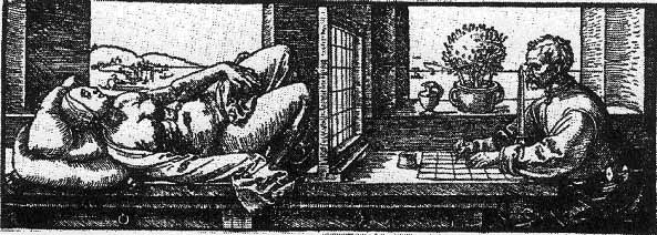
     The teaching help called "Master Picture Plane" demonstrates clearly the virtual picture plane imagined in front of us, being as far as our streched arm reaches. During the process of sketching we take over from this notable plane the data of perspective distortion to our drawing plane.
     This taking over of known facts of structure should be accomplished through a comparing analysis and not through mechanical "copying".
     The framing picture of the first rough sketch contains a part of the proportion-ratio to which the fraction number of observed obliquity we connect.
     I propose to practise with my device mainly at the beginning of learning process to keep better in mind the mass of data described above.


The procedure of taking over of observed proportion of slanting to the Drawing Plane. We use the smaller side of right angle as a comparing unit


Testing my teaching help mounted on an artist's easel. The slanting of eaves observed through the grid of Master Picture Plane (Göd, Autumn of 2000)


 © All rights reserved Associated Professor Balazs Mehes PhD
recommended resolution 1024×768