
Perspective
¤ Basic Concepts of Linear Perspective
¤ "Illustrated Drawning of Cubic Forms"
¤ "The Master Picture Plane"
¤ Reflected Tower Trio
¤ Circular Rings
¤ Furniture Drawing
¤ Corridor Drawing
Constructions
Outdoor Assignments
Special Courses
Publications
REFLECTED TOWER TRIO |
|||||||||
Basic Cases of Perspective |
|||||||||
|
|||||||||
Key-words: Convergence, Extreme Oblique Line, Foreshortening, Framing Shape, Front Plane, Grid Point, Horizon, Lateral Sides' Ratio, Negative Triangle, Object's Picture Plane, Oblique Line of In-between, Orthogonal Picture, Principal Direction, Principal Visual Ray, Proportion, Sight from Above, Sight from Below, Structural Grid of Basic Lines, Vanishing Point, View-Point, Visual Cone. |
|||||||||
Creating the structure of perspective, in Architectural Freehand Drawing we simplify volumes and spaces by enveloping them into framing shapes. The formation of framing shapes consists of a transparent grid composed of framework cubes. Within the perspective picture, reality's parallels seem to converge into a distant Vanishing Point. While gradually approaching to this rectangular system we soon recognize that some vanishing points seem to glide out our visual cone! To their possible position extreme oblique lines relate. |
|||||||||
| BIRTH OF PERSPECTIVE | |||||||||
| I - Phenomena: Convergence, Foreshortening | |||||||||
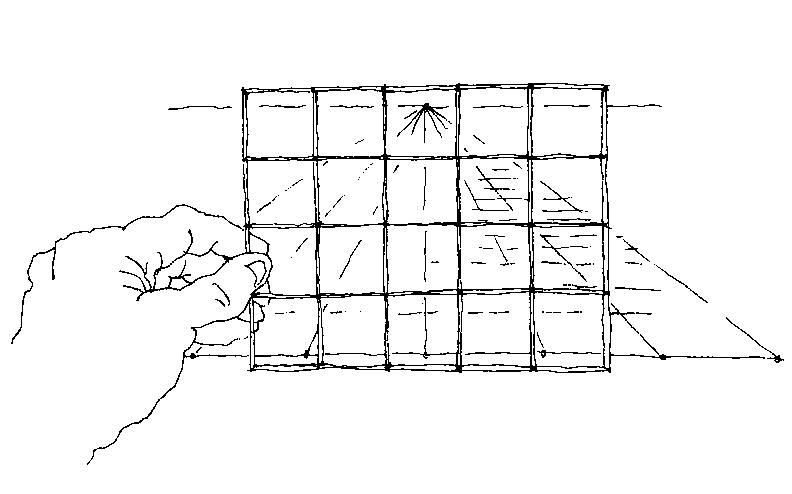
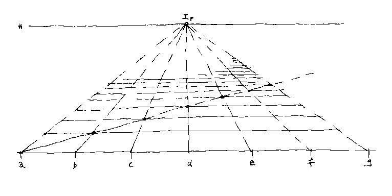
We reduce our environment to vertical and horizontal planes outfitted with a square net. Let us first examine the floor's network - through a quadric grid held vertically! What do we see? Longitudinal joints are converging. The only subdivision which seems to remain vertical intersects our Vanishing Point on the Horizon. Horizontal subdivisions remain parallel but going backwards interim distances are diminishing. Moving off the Horizon, subdivision distances are increasing. The originally equal row widths of network seem to become narrower backwards. Moving off the central vertical subdivision, the virtual slanting of longitudinal lines grows. Even the diagonals of the square net (being parallel in reality) seem to converge. These diagonals will run toward their own Vanishing Point. With the help of the first diagonal, we may comfortably construct near grid points on the floor plane as shown on Fig. 2. |
|||||||||
|
|||||||||
|
|||||||||
2. Components of floor's network - The case of Single Vanishing Point Perspective |
|||||||||
Lateral subdivisions (equal by rows) becoming narrower backwards, longitudinal lines converge. Horizon and Vanishing Point. Diagonal construction of near grid points. |
|||||||||
| I / a - Finding of horizon | |||||||||
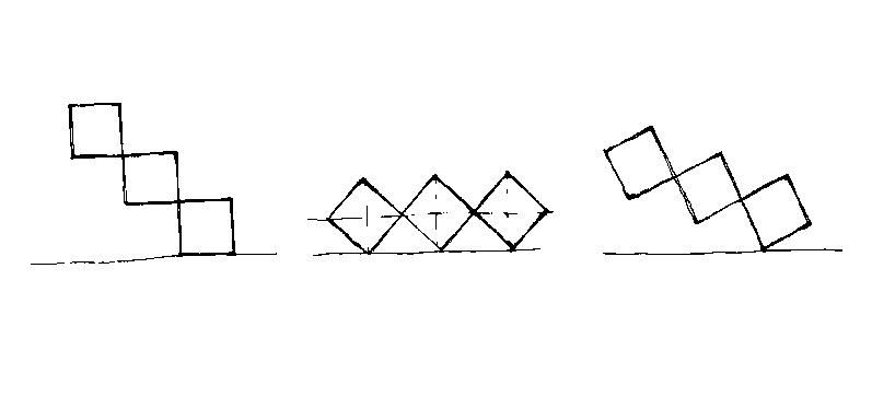
It would be difficult to guess the horizon's height without a solid vertical scale. Following the original floor subdivisions, let's vertically raise imaginary walls equipped with squares! Now, at positive and negative corners, we may observe the changing of the surface grid. Where reality's horizontal lines fall in a single line (that means that the zigzagging stops) will the Horizon belonging to our position be. |
|||||||||
|
|||||||||
| II - Causes: Perspective as Central Projection | |||||||||
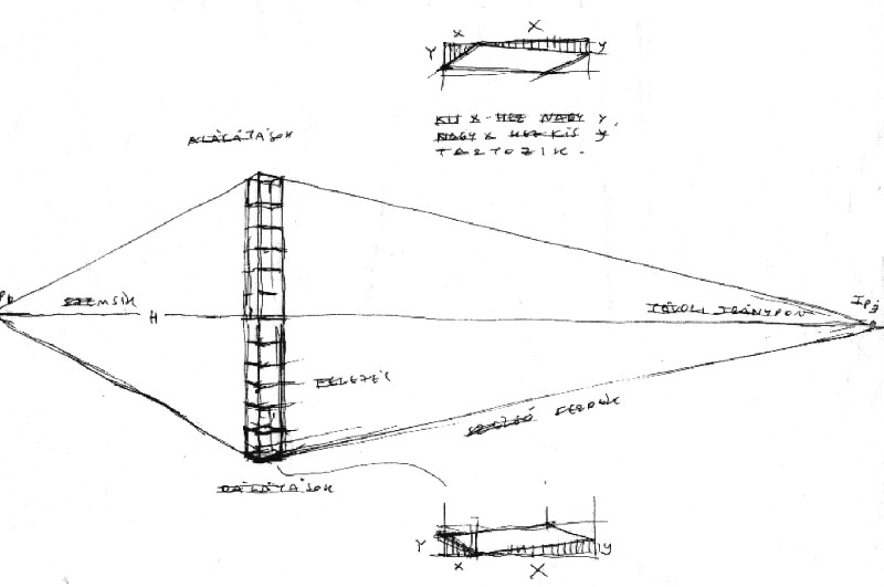
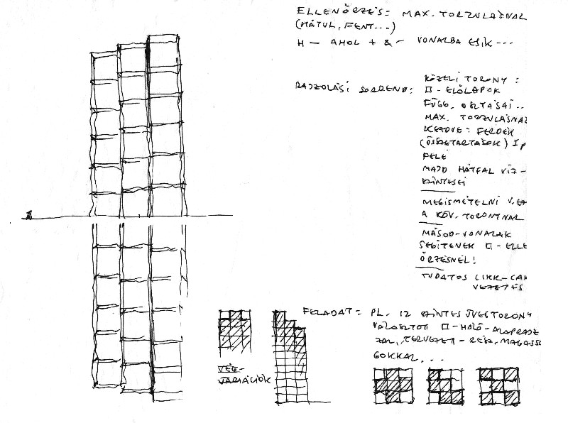
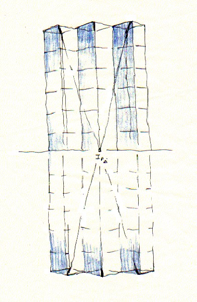
In the history of perspective rendering the original problem was how to depict an opening door. (Early solutions are shown e.g. on Greek vases.) Artists of the Renaissance - Alberti, Brunneleschi, Dürer and others - looking through the web of a weaving loom, discovered the geometry in perspective. We should get acquainted with basic rules by studying of framework cubes. DIAGONALLY POSITIONED TOWER TRIO WITH ITS MIRROR PICTURE Let's examine regular prisms positioned in a diagonal row! Let's place the model on a reflecting water surface and walk around!! Our tower trio seems to be appropriate for studying basic phenomena of perspective distortions. Considering the relation between the observer's position and the subject's front plane, we may distinguish three basic cases. They are the parallel (frontal), the symmetrical (diagonal) and the general cases. |
|||||||||
|
|||||||||
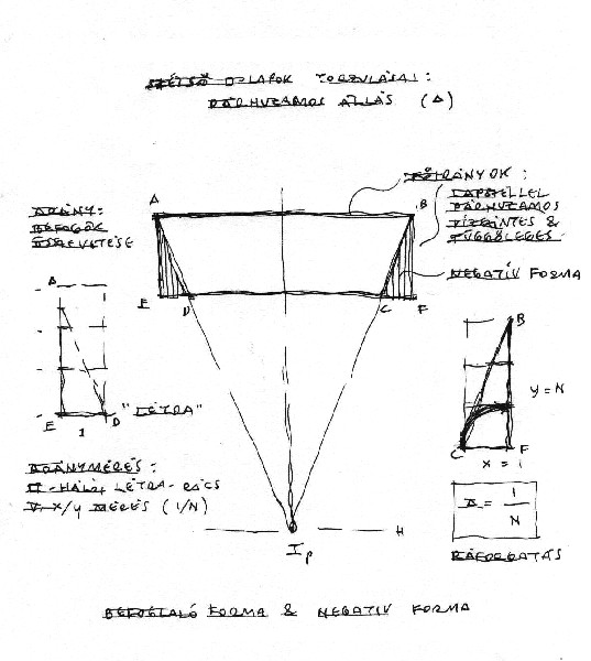
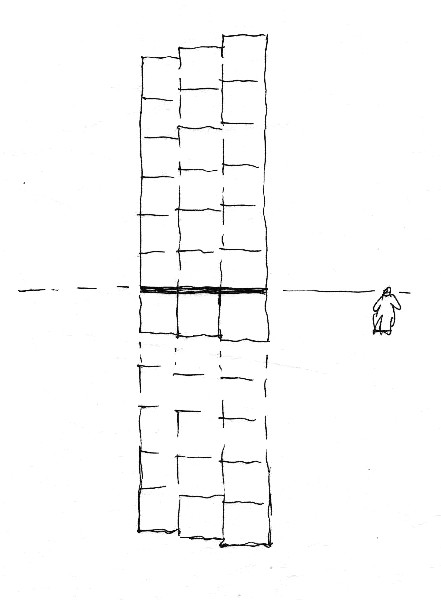
4. Basic data - A solo tower with its reflection seen from afar (Parts of the figure: Vanishing Points, increased extreme planes, view from above, view from below, extreme oblique lines and oblique lines of in-between) |
|||||||||
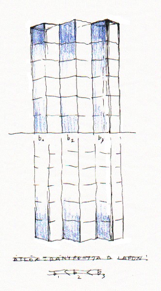
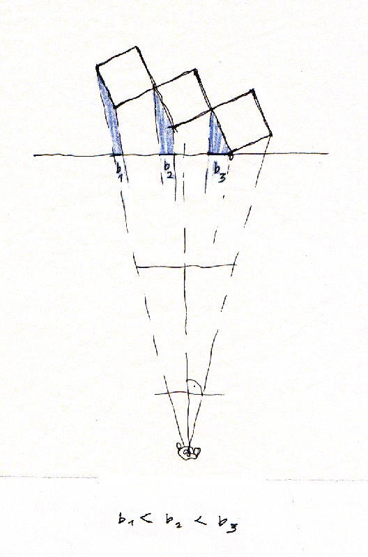
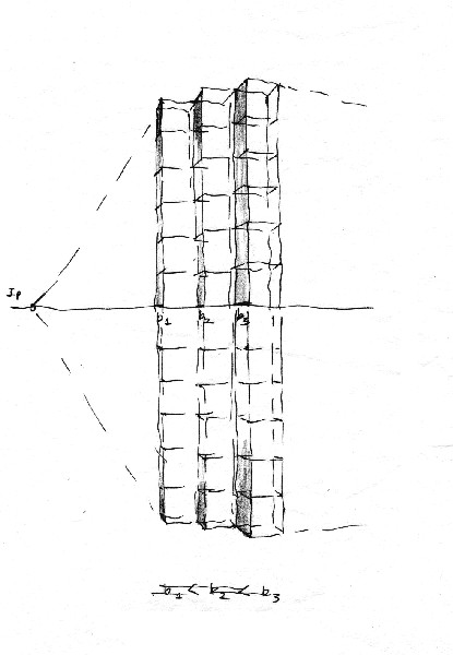
Both vanishing points happen to stay on the same paper only if the object is rather tiny (that means it is seen from a big distance) or the paper is extremely large. RELATION BETWEEN OBJECT'S FRONT PLANE AND OBSERVER'S PICTURE PLANE The number of vanishing points belonging to the structural grid is up to us! Standing frontally, we'll have a solo vanishing point. Walking around the tower, we'll have to do with two vanishing points. Approaching to the tower, even verticals start slanting - a third vanishing point will appear. We'll better understand the changing of horizontal distances between verticals (called as lateral sides' ratio) if we know the connection between the picture plane and the relevant frontal plane. While creating perspective, we ought to keep in mind the site plan (top view) as well. |
|||||||||
|
|||||||||
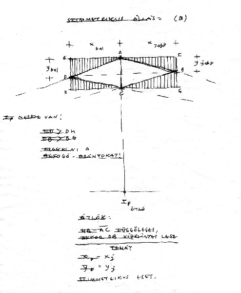
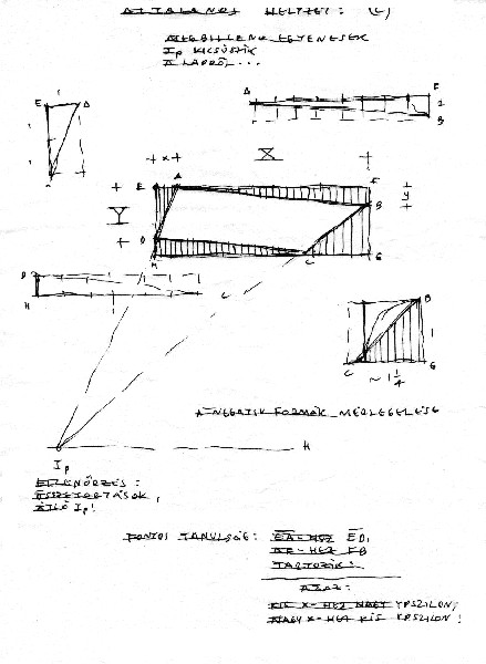
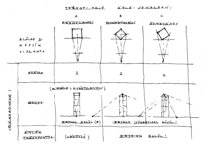
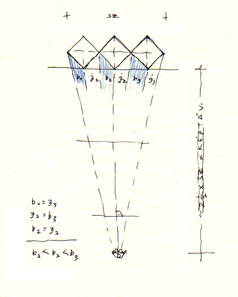
5. Three basic cases on relation between front and picture plane (F / P) (A) Frontal view (F is parallel to P) - single vanishing point perspective (B) Diagonal view (P is perpendicular to the diagonal) - symmetric case, two Vp (C) General view (F is not parallel to P) - two vanishing points |
|||||||||
|
|||||||||
6. Chart on relation between front plane and picture plane |
|||||||||
| PARALLEL CASE (A) | |||||||||
|
|||||||||
|
|||||||||
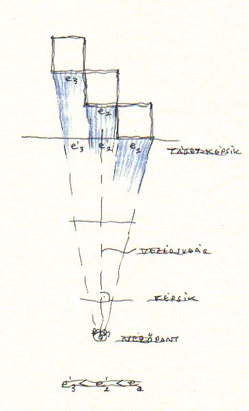
Next let's change the place of Horizon! When lifting our Horizon off the floor's level, a soft transition between object- and volume- (or space-) drawing will be realized. At object drawing views from above are more often, at space drawings views from below can't be avoided. One side product of our analysis is Fig. 10: the key for scale changing is hidden within the moving of Horizon. |
|||||||||
| SYMMETRIC CASE (B) | |||||||||
|
|||||||||
|
|||||||||
| GENERAL CASE (C) | |||||||||
|
|||||||||
|
|||||||||
16. Overview of distortions belonging to structural grid's horizontal planes |
|||||||||
Chart's central row shows the movement of Vanishing Point on the Horizon as seen by the Observer walking around the tower. In the course of walking around, the moving Vanishing Point of squares' edges is slowly getting off our visual cone. Meanwhile (as a comfort) the Vanishing Point of Diagonals gradually enters. Due to the fact that squares' diagonals in reality are parallel, they'll also own a Vanishing Point in perspective. |
|||||||||
| III - Distortion of extreme planes - Details | |||||||||
Approaching to the view, we nay finalize details through thorough fully analysis of details. Distortions belonging to extreme planes ought to be determined with the help of framing shape's negative triangles. The framing shape is a rectangle having right angles parallel to paper's corners. After having examined all negative triangles of the framing shape, the slanting of extreme oblique lines might be translated into treatable numbers. |
|||||||||
|
|||||||||
|
|||||||||
|
|||||||||
SUMMARY |
|||||||||
We reduce the world of objects into a structural grid of transparent cubes. Through analyzing the relation between a tower's front plane and the observer's picture plane, we distinguish three basic cases of perspective. They are: the frontal (parallel), the diagonal (symmetrical) and the oblique (general) case. In perspective, the real world's parallel lines seem to converge into a distant Vanishing Point. If these parallels lay on horizontal planes, their Vanishing Point will also stay on the Horizon. The number of vanishing points is up to our standing position. Some vanishing points happen to be afar of drawing paper's edge. Yet within our simplified cubic structure, extreme oblique lines clearly point toward hidden vanishing points. In lack of direct Vanishing Points, but knowing the horizon's position, we may employ the Diagonals' Vanishing Point for controlling essential framework points. Preliminarily chosen object's dimensions and one Vanishing Point do consequently determine the other Vanishing Point's position. |
|||||||||
|
|||||||||
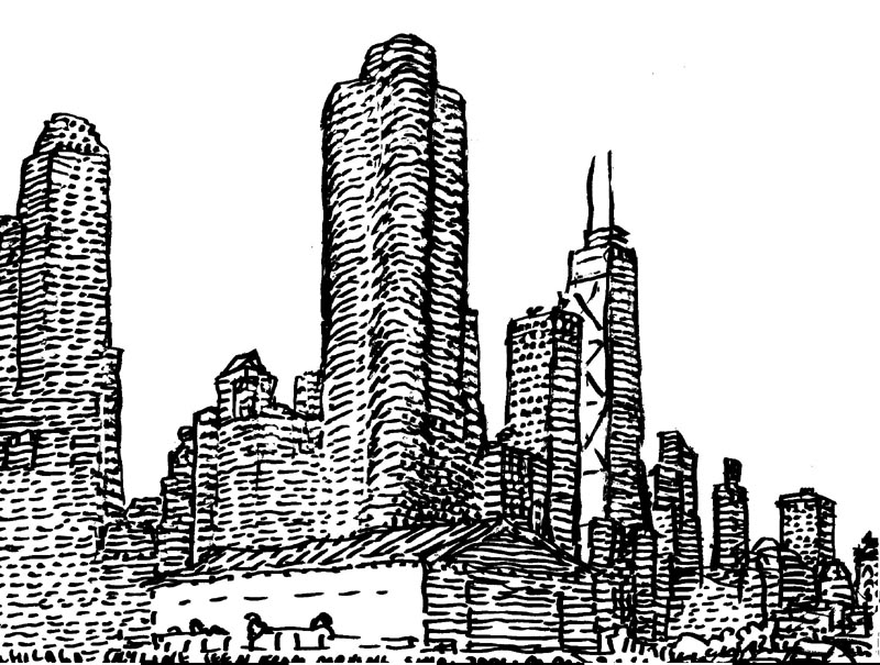
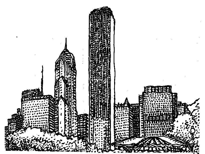
Balazs Mehes: Chicago skyline as seen from a moving ship, 2001 (felt pen) |
|||||||||
© All rights reserved Associated Professor Balazs Mehes PhD recommended resolution 1024×768 |
|||||||||

.jpg)
.jpg)